
Using RSEmulate 5000
Emulate 5000 is a program that runs on your PC which allows us to simulate downloading and going online with an actual processor. We can use Emulate 5000 to check blocks of a project before making changes to a live system. Emulate 5000 comes with the Full version of Studio 5000. This tutorial will walk you though how to create a project and add I/O for testing purposes.
Step 1 — Open Emulate 5000
If you do not have a shortcut on your desktop, go to Start | All Programs | Rockwell Software, and open Emulate 5000.
Step 2 — Add your processor
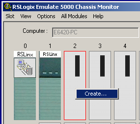
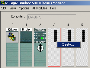
Right click on slot 2, and choose “Create”.
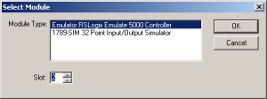
Select the Emulator Controller, then press “OK”. (We will leave the slot number at default — slot 2)
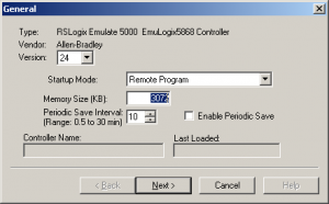
On the next dialog box, we will leave the settings at default to simplify this example. Notice the version is “24” in this case. Press “NEXT”.
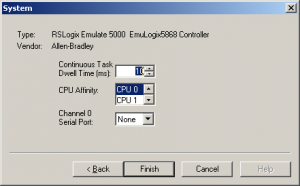
On the next window, we will again leave the settings at default, and press “Finish”
Step 3 — Add the Simulator Modules
Right click on slot 3, and create a new module.
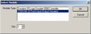
Choose the 1798-SIM module. Press “OK”.
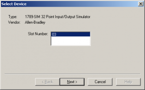
Choose Slot 3, and press “NEXT”.
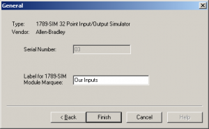
In the Marquee, type “Our Inputs”, and press “FINISH”.
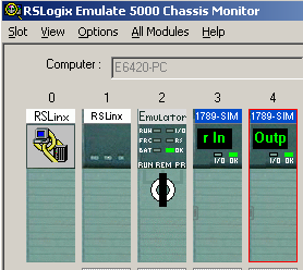
Repeat this procedure to add another SIM module to slot 4. The marquee on the new module will read “Our Outputs” When finished, your simulator should appear as follows:
Step 4 — Creating the Studio 5000 Project
Next, open Studio 5000. If you don’t have a shortcut, this will be under Start | All Programs | Rockwell Software, and we will create a new project.

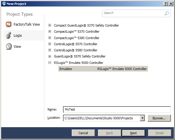
We will choose to create a Logix project, and select the Emulator processor as shown. We’ll just name this project “MyTest”, then press “NEXT”.
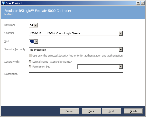
The version will be “24”. This must match the version of the Emulator that we selected when adding the processor to the Emulate Chassis. The Emulate 5000 chassis is 17 slots, and our processor is in slot 2 of the Emulate 5000 chassis. The project name is “MyTest”. Be sure all of this information is correct, and press “Finish”.
Step 5 — Add the I/O (Simulator Modules)
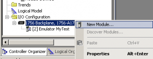
Right click the backplane under I/O Configuration, and select “New Module”
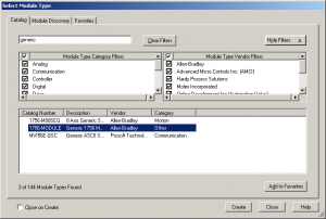
Next, we will select a generic module (1756-MODULE), then press “Create”
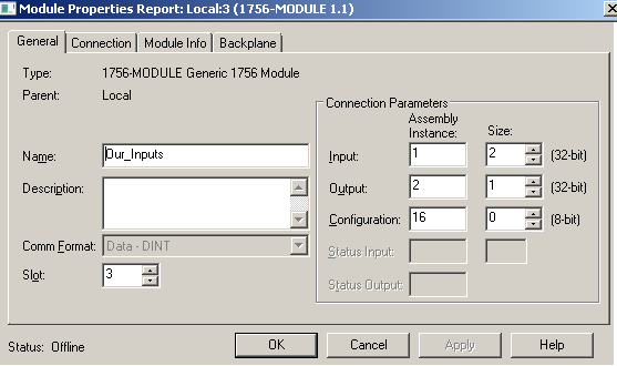
Complete the dialog box as follows. Recall that our first simulator module is in slot #3. Be sure to complete the Assembly instance and size correctly (as shown), then press “OK”.
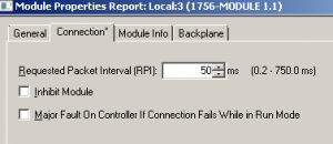
Set the Requested Packet Interval (RPI) at 50ms. The module will not function properly if this is set below this value.
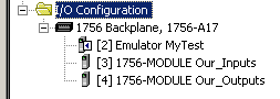
Repeat this procedure (Step 5) to add the Simulator module to Slot #4. The name of this new module will be “Our Outputs”.
When finished, our I/O Configuration will appear as follows:
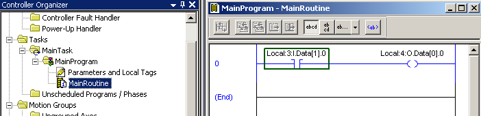
Step 6 — Add our Logic
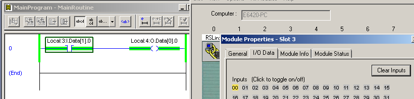
We will keep this very simple. Under the MainTask, in the MainProgram, in the Mainroutine, we will add our logic as follows:
Step 7 — Configure Communication in RSLinx Classic
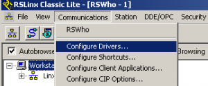
Open RSLinx communication server. If you don’t have a shortcut to RSLinx, you can get to RSLinx by going to Start | All Programs | Rockwell Software | RSLinx | RSLinx Classic
Click on Communications | Configure Drivers.
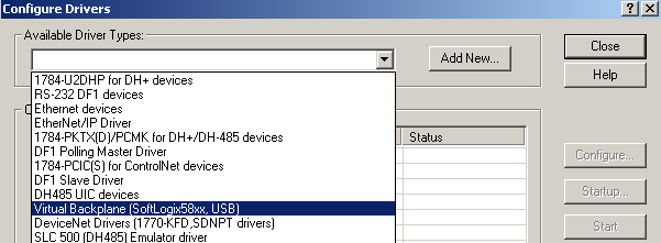
From the available driver types, menu, we will select “Virtual Backplane”, then press “Add New”
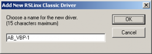
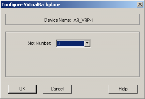
Here, we’ll leave the name of the virtual backplane at default, and press OK.
We will use Slot 0 of the Virtual Chassis as our location for the RSLinx Driver.
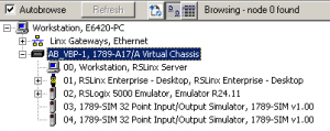
Close the Configure Driver screen, and we can verify communication using RSWho (Under Communications | RSWho). Just press the + next to the virtual backplane driver, and you should see our processor and simulator modules that we created earlier.
Step 8 — Download your project.
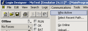
Back in Studio 5000, we must create a path to download our project. Click Comms | Who active from the menubar.
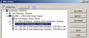
Browse to your Emulator PROCESSOR and press “Download” It must be the PROCESSOR that you highlight before pressing “Download”, then another dialog box will appear asking you to verify that you want to download.
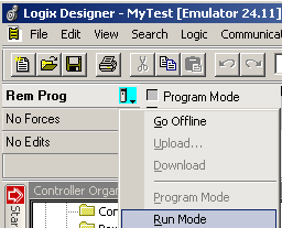
Place the processor in “Run” mode, then you will be asked to verify that you want to go to RUN.
Step 9 — Test your work.
Open the Emulate 5000 Chassis Monitor, and go to the properties of the module in slot 3. On the I/O Data tab, energize input 0. When you energize this bit, you will see that your logic is true.
— Ricky Bryce